Piping drawings, also known as piping plans or schematics, are technical drawings that show the layout and design of a piping system. They are used to guide the installation, maintenance, and repair of the system. These drawings typically include the following information:
- Pipe sizes and materials
- Fittings (elbows, tees, valves, etc.) and their locations
- Pipe routing and elevation changes
- Pipe supports and hangers
- Flow direction and process flow
- Equipment and instrumentation connections
- Any special requirements or considerations (such as insulation or coatings)
Piping drawings can be created using computer-aided design (CAD) software, and may also include isometric views or 3D models to better visualize the system. These drawings must be accurate and clear, as they are used as a reference for the construction, operation, and maintenance of the piping system.

Types of Piping Drawings
There are several types of piping drawings, including:
- Piping layout drawings: These show the overall arrangement of the piping system, including the location of equipment, valves, and other components.
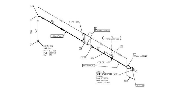
- Isometric drawings: These are three-dimensional representations of piping systems, showing the exact location and orientation of all components.
- Detail drawings: These provide more detailed information about specific components of the piping system, such as flanges, valves, and pipe supports.
- P&ID (Piping and Instrumentation Diagrams): These diagrams provide a detailed overview of the process flow, including the location and type of process equipment, as well as the flow direction and process conditions.
- Construction drawings: These drawings provide detailed information on the construction and installation of the piping system, including information on materials, tolerances, and fabrication.
- As-built drawings: These are updated versions of the original construction drawings that reflect any changes made during the construction and installation process.
Piping Plan Drawings/General Arrangement Drawings ?
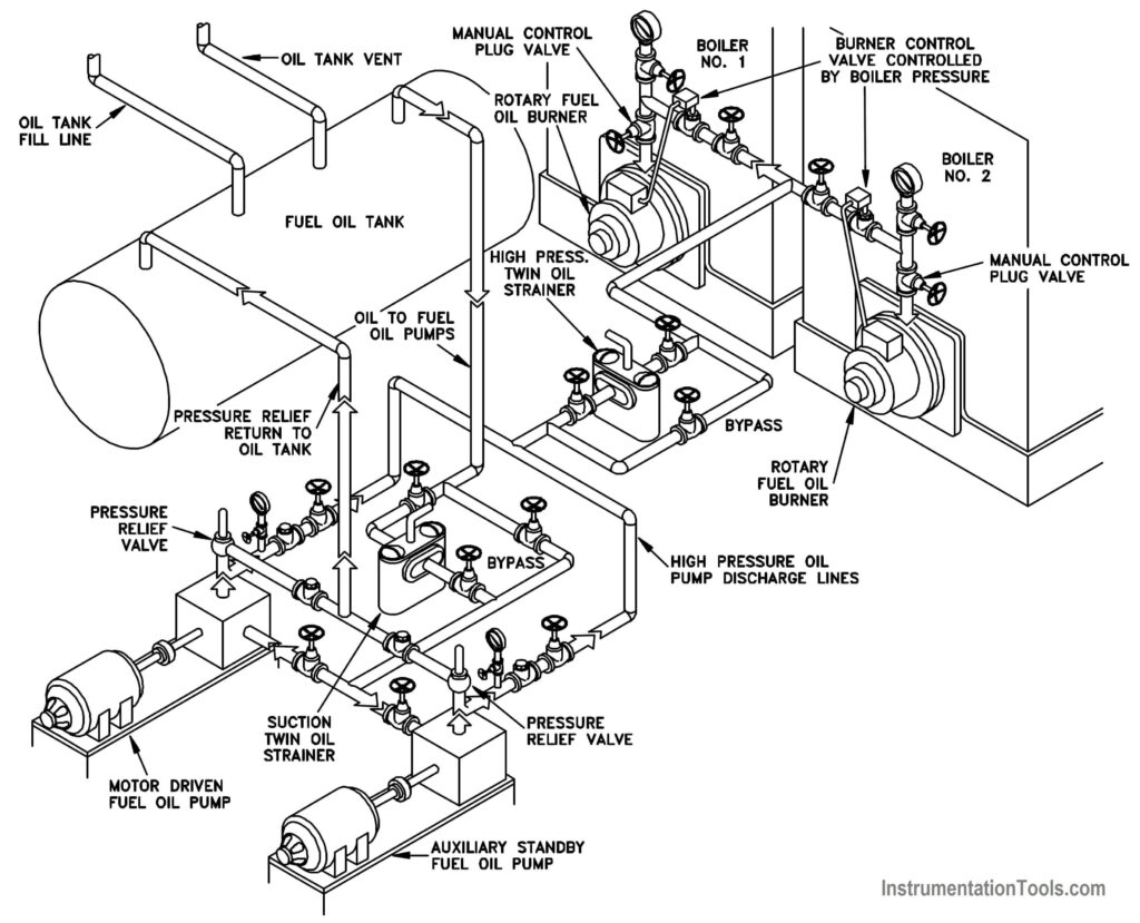
Piping plan or general arrangement drawings are a type of piping drawing that show the overall layout and arrangement of a piping system. These drawings typically include the location of equipment, valves, and other components, as well as the routing of the pipes throughout the facility. They also provide information on the relative elevations of the components and the direction of flow through the system. The objective of the piping plan drawing is to give an overall view of the system, so that the designer and the installer can understand how the system will function as a whole. Additionally, it allows for easy identification of any interference, both spatial and functional, that may occur between different systems.
Process Flow Diagrams
A process flow diagram (PFD) is a graphical representation of a process, showing the individual steps and the inputs and outputs at each stage. PFDs are commonly used in chemical and process engineering to document and analyze process systems. They typically include symbols to represent process equipment and lines to show the flow of materials and energy through the system. PFDs can be used to identify bottlenecks and inefficiencies in a process and to develop process control and improvement strategies. They are also used to communicate the process design to stakeholders and as a training tool for operators and maintenance personnel.
PFDs typically include the following elements:
- Process equipment such as tanks, vessels, heat exchangers, pumps, compressors, and others
- Piping and instrumentation, including valves and flow meters
- Control systems, including instrumentation and control valves
- Process flow lines and arrows indicating the direction of flow
- Process conditions such as temperature, pressure, and flow rates
- Process flowrate and material balance information
PFDs are typically used in conjunction with other types of process diagrams such as Piping and Instrumentation Diagrams (P&IDs) and process control narratives.
Piping & Instrumentation Diagram
A Piping and Instrumentation Diagram (P&ID) is a type of engineering diagram that shows the process flow for an industrial process. It is a detailed diagram that includes all major components of the process, such as equipment, pipes, valves, and control systems. The P&ID is used to understand the process flow and to identify potential problems or inefficiencies in the process. It also provides the instrumentation and control schemes for the process.
P&IDs typically include the following elements:
- Process equipment such as tanks, vessels, heat exchangers, pumps, compressors, and others
- Piping and instrumentation, including valves and flow meters
- Control systems, including instrumentation and control valves
- Process flow lines and arrows indicating the direction of flow
- Process conditions such as temperature, pressure, and flow rates
- Electrical power, control and communication connections
- Safety and shutdown systems
- Identification of all the instruments used in the process, including the type, range, and measurement units.
P&IDs are typically used in the design, construction, and maintenance of chemical, oil and gas, power plants, food and pharmaceutical processes, as well as in many other industries. They are commonly used in conjunction with other types of process diagrams, such as Process Flow Diagrams (PFDs) and process control narratives.
Working of Piping Drawings
Piping drawings, also known as piping plans or piping schematics, are detailed diagrams that show the layout and routing of pipes, valves, and other equipment in a process or mechanical system. They are used to communicate the design of a piping system to engineers, contractors, and other stakeholders, and to guide the installation, operation, and maintenance of the system.
Piping drawings typically include the following elements:
- A legend or key, which explains the symbols and notations used on the drawing
- A list of materials, including the type, size, and schedule of the pipes and fittings
- A bill of materials, which lists the specific components and equipment used in the system
- Isometric views, which show the 3D layout of the pipes and equipment in the system
- Orthographic views, which show the 2D layout of the pipes and equipment in the system
- Sections and details, which show close-up views of specific components and connections
- Piping and instrumentation diagrams (P&IDs), which show the flow of materials and energy through the system, including the location and type of valves, pumps, and other equipment
Piping drawings also include important information about the design and construction of the system, such as the location and type of supports, the slope of the pipes, and the location of tie-ins to existing systems. They also show the location of valves and other controls, which are used to regulate the flow of materials and energy through the system. The drawings will be usually prepared in CAD software like AutoCAD or Solidworks and it will be used as a guide for the construction and installation of the piping system.
Overall, piping drawings are an essential tool in the design, construction, and operation of process and mechanical systems, providing detailed information about the layout and routing of pipes, valves, and other equipment, and serving as a guide for the installation, operation, and maintenance of the system.
Plot Plan Layout
A plot plan layout is a detailed diagram that shows the layout of a piece of land, including the location of buildings, structures, parking areas, roads, walkways, and landscaping. It is typically used to show the layout of a construction site, including the location of buildings and other structures, as well as the location of utilities and other services.
A Plot Plan layout typically includes the following elements:
- Property lines and boundaries
- Buildings and other structures
- Parking areas and driveways
- Roads, sidewalks and walkways
- Landscaping, including trees and other vegetation
- Utilities, such as water, gas, and electrical lines
- Stormwater management features
- Fire lanes, emergency access points and evacuation routes
- Other features such as swimming pools, playgrounds, and recreational areas
Plot plan layouts are used in the design and construction of buildings and other structures, as well as in the planning and development of land. They are also used for zoning and permitting purposes, and as a tool for contractors, engineers, and other professionals to visualize the site and plan for construction activities.
Advantages and Disadvantages of Piping Drawings
Advantages of piping drawings include:
- They provide a clear and detailed representation of the piping system, making it easier to understand and communicate the design to engineers, contractors, and other stakeholders.
- They allow for the identification and resolution of potential issues or conflicts in the design before construction, reducing the risk of errors and delays during the construction process.
- They can be used as a guide for the installation, operation, and maintenance of the system, ensuring that the system is built and operated correctly.
- They provide a reference for future maintenance, troubleshooting and modification of the piping system.
- They can be used for cost estimation and budgeting for the project.
Disadvantages of piping drawings include:
- They require a significant amount of time and resources to create, especially for complex systems.
- They can be difficult to read and interpret for non-experts or those unfamiliar with the symbols and notations used.
- They may not accurately reflect the as-built conditions of the piping system, so it is important to verify and update the drawings as needed.
- There is a risk of errors or omissions in the drawings, which can lead to problems during construction or operation of the system.
- They are usually only in 2D, this makes it difficult to understand the 3D layout of the system
Overall, while piping drawings can be a valuable tool in the design and construction of a piping system, they also require a significant investment of time and resources and have the potential for errors. It’s important to use them in conjunction with other design tools and resources, and to verify and update the drawings as needed throughout the construction process to ensure the accuracy and effectiveness of the system.