Free Body Diagram: Definition, Purpose, Examples, Steps
A free body diagram (FBD) is a pictorial representation of an object and the forces acting on it. It is used to simplify and analyze the forces acting on a body in order to determine the net force and the acceleration of the object.
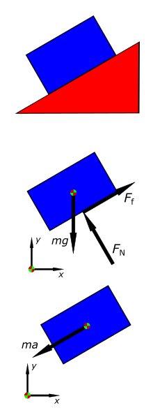
To create a free body diagram, the object is isolated from its surroundings and all external forces acting on it are represented by arrowed lines. The direction of the arrow represents the direction of the force and the length of the arrow represents the magnitude of the force. The object is typically represented as a simple geometric shape, such as a rectangle or a circle.
The forces acting on the object can be divided into two categories: contact forces and non-contact forces. Contact forces, such as friction and tension, are forces that are in physical contact with the object. Non-contact forces, such as gravity and air resistance, act on the object from a distance.
When analyzing a free body diagram, the net force (also called the resultant force) is found by adding up all of the forces acting on the object. The net force is the overall force acting on an object and is what causes the object to accelerate. The acceleration of the object can then be determined using Newton’s second law of motion, which states that the net force acting on an object is equal to the object’s mass multiplied by its acceleration (F=ma).
In summary, a free body diagram is a useful tool for analyzing the forces acting on an object and determining the net force and acceleration of the object. It is a visual representation of an object and the forces acting on it, and it can be used to simplify and analyze complex systems.
Purpose of the Free Body Diagram
The primary purpose of a free body diagram (FBD) is to analyze the forces acting on an object and to determine the net force and acceleration of the object. It serves as a visual representation of the forces acting on an object and can be used to simplify and organize the information, making it easier to understand and analyze.
FBDs are often used in physics and engineering to study the motion and stability of an object. By isolating the object from its surroundings and representing all of the external forces acting on it, a FBD makes it possible to analyze the forces acting on an object in isolation. This allows for the determination of the net force acting on the object, and the acceleration of the object can be determined using Newton’s second law of motion.
Additionally, FBDs are often used to study the internal forces acting within a structure, such as a bridge or a building. By representing all of the internal forces acting on a structure, engineers can determine the forces acting on each part of the structure and ensure that the structure is stable and able to withstand the forces acting on it.
FBDs can also be used to solve problems related to forces and motion in a variety of fields such as mechanics, robotics, and biomechanics. In these fields, FBDs are used to study the motion and stability of mechanical systems and to design new systems.
In summary, the purpose of a Free Body Diagram is to provide a visual representation of the forces acting on an object and to use it to analyze the net force and acceleration of the object. It is a powerful tool that simplifies the analysis of complex systems in fields such as physics, engineering, mechanics, robotics and biomechanics.
Drawing a Free-Body Diagram
Drawing a free-body diagram (FBD) is a process of creating a visual representation of an object and the forces acting on it. The following steps can be followed to draw an accurate and informative FBD:
- Isolate the object: The first step is to isolate the object from its surroundings. This means that all external factors that may affect the object’s motion should be ignored and only the object and the forces acting on it should be considered.
- Identify the forces acting on the object: Next, identify all of the forces acting on the object. This includes contact forces, such as friction and tension, as well as non-contact forces, such as gravity and air resistance.
- Represent the forces: Represent the forces acting on the object using arrowed lines. The direction of the arrow represents the direction of the force and the length of the arrow represents the magnitude of the force. Draw the forces acting on the object with the tail of the arrowhead touching the object.
- Label the forces: Label each force with its name or symbol. This will make it easier to identify and analyze the forces later.
- Draw the object: Draw the object as a simple geometric shape, such as a rectangle or a circle. Label the object with its name or symbol.
- Indicate the reference direction: Indicate the reference direction, such as up or down, left or right, to indicate the direction of gravity.
- Check and review: Review the diagram to ensure that all forces acting on the object are represented, and the reference direction is correct. Also, make sure that the length and direction of the force vectors are accurate.
In summary, to draw a Free Body Diagram, you need to isolate the object, identify the forces acting on it, represent the forces using arrowed lines, label the forces, draw the object, indicate the reference direction and review the diagram. A well-drawn FBD should be simple, clear and easy to understand and should accurately represent the forces acting on the object.
Types of Forces for Free Body Diagram
There are two main types of forces that can act on an object: contact forces and non-contact forces.
- Contact forces: Contact forces are forces that are in physical contact with the object. They can be further divided into three categories:

- Normal force: The normal force is the force exerted by a surface perpendicular to the object in contact with it. For example, the normal force exerted by a table on a book.
- Friction force: Friction force is the force that opposes motion between two surfaces in contact. There are two types of friction force: static friction and kinetic friction. Static friction acts to prevent an object at rest from moving, while kinetic friction acts to oppose the motion of an object that is already moving.
- Tension force: Tension force is the force exerted by a rope or cable when it is pulled tight. Tension force is a contact force that acts along the length of the rope or cable.
- Non-contact forces: Non-contact forces are forces that act on an object from a distance. They can be further divided into three categories:
- Gravitational force: Gravitational force is the force exerted by the earth on an object. It is a non-contact force that acts in the downward direction.
- Electric force: Electric force is the force exerted by electric charges. Electric force can be either attractive or repulsive, depending on the charges.
- Magnetic force: Magnetic force is the force exerted by magnets. Like electric force, magnetic force can be either attractive or repulsive, depending on the poles of the magnets.
In summary, there are two main types of forces that can act on an object: contact forces and non-contact forces. Contact forces are forces that are in physical contact with the object, examples of which include normal force, friction force, and tension force. Non-contact forces are forces that act on an object from a distance, examples of which include gravitational force, electric force, and magnetic force.
Free Body Diagram Examples
Free body diagrams (FBDs) are used to represent the forces acting on an object. Here are a few examples of how to create a FBD for different scenarios:
- A book resting on a table:
- Isolate the object: The book is isolated from its surroundings.
- Identify the forces acting on the object: The forces acting on the book are gravity (acting downward) and the normal force (acting upward) exerted by the table.
- Represent the forces: The force of gravity is represented by an arrow pointing downward and the normal force is represented by an arrow pointing upward.
- Label the forces: Label the force of gravity as “W” and the normal force as “N”.
- Draw the object: Draw the object as a rectangle and label it as “book”.
- Indicate the reference direction: Indicate the reference direction as down.
- Check and review: Check to make sure that the arrowheads are pointing in the right direction and that the labels are correct.
- A person pushing a box across a floor:
- Isolate the object: The box is isolated from its surroundings.
- Identify the forces acting on the object: The forces acting on the box are the applied force (acting in the direction of the push), the force of friction (acting in the opposite direction of the push), and the force of gravity (acting downward).
- Represent the forces: The applied force is represented by an arrow pointing in the direction of the push, the force of friction is represented by an arrow pointing in the opposite direction of the push, and the force of gravity is represented by an arrow pointing downward.
- Label the forces: Label the applied force as “Fapp”, the force of friction as “friction”, and the force of gravity as “W”.
- Draw the object: Draw the object as a rectangle and label it as “box”.
- Indicate the reference direction: Indicate the reference direction as down.
- Check and review: Check to make sure that the arrowheads are pointing in the right direction and that the labels are correct.
- A hanging object:
- Isolate the object: The object is isolated from its surroundings.
- Identify the forces acting on the object: The forces acting on the object are the tension force (acting in the upward direction) and the force of gravity (acting downward).
- Represent the forces: The tension force is represented by an arrow pointing upward and the force of gravity is represented by an arrow pointing downward.
- Label the forces: Label the tension force as “T” and the force of gravity as “W”.
- Draw the object: Draw the object as a shape and label it.
- Indicate the reference direction: Indicate the reference direction as down.
- Check and review: Check to make sure that the arrowheads are pointing in the right direction and that the labels are correct.

In summary, these examples show how to create a Free Body Diagram for different scenarios. The process includes isolating the object, identifying the forces acting on it, representing the forces using arrowed lines, labeling the forces, drawing the object, indicating the reference direction and reviewing the diagram. A well-drawn FBD should be simple, clear and easy to understand and should accurately represent the forces acting on the object.
Working of Free Body Diagram
A free body diagram (FBD) is used to represent the forces acting on an object and to analyze the net force and acceleration of the object. The following steps can be used to work with a FBD:
- Isolate the object: The first step is to isolate the object from its surroundings. This means that all external factors that may affect the object’s motion should be ignored and only the object and the forces acting on it should be considered.
- Identify the forces acting on the object: Next, identify all of the forces acting on the object. This includes contact forces, such as friction and tension, as well as non-contact forces, such as gravity and air resistance.
- Determine the net force: The net force is found by adding up all of the forces acting on the object. The net force is the overall force acting on an object and is what causes the object to accelerate.
- Determine the acceleration of the object: The acceleration of the object can be determined using Newton’s second law of motion, which states that the net force acting on an object is equal to the object’s mass multiplied by its acceleration (F=ma). By solving for acceleration, we can calculate the acceleration of the object.
- Analyze the forces acting on the object: Once the net force and acceleration have been determined, it is possible to analyze the forces acting on the object in more detail. This includes determining the effect of individual forces on the object’s motion and the relative magnitude of the forces.
- Draw the Free Body Diagram: Once you have determined the net force and acceleration of the object, you can then draw the Free Body Diagram to represent the object and the forces acting on it.
In summary, to work with a Free Body Diagram, you need to isolate the object, identify the forces acting on it, determine the net force and acceleration of the object, analyze the forces acting on the object and draw the Free Body Diagram. By working with a Free Body Diagram, we can simplify and analyze complex systems, and understand the forces acting on an object and the effect of these forces on its motion.